How to Wire a ASC Mark 3 Photovoltaic Charge Controller

When it comes to setting up a photovoltaic (PV) system, proper wiring is crucial for the efficient and safe operation of the system. The ASC Mark 3 photovoltaic charge controller is a key component in managing the charging of your PV batteries. In this article, we will discuss the steps to wire a ASC Mark 3 photovoltaic charge controller.
Step 1: Gather the Necessary Tools and Equipment
Before you begin, make sure you have all the required tools and equipment. This may include wire cutters, wire strippers, a screwdriver, and the ASC Mark 3 manual.
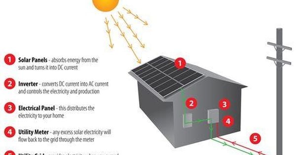
Step 2: Understand the ASC Mark 3 Wiring Diagram
Take the time to thoroughly review the wiring diagram provided in the ASC Mark 3 manual. This will give you a clear understanding of how the charge controller should be wired within the PV system.
Step 3: Connect the Solar Panels
Start by connecting the solar panels to the ASC Mark 3 charge controller. Use the appropriate gauge of wire and make sure to follow the polarity markings on the controller. This will ensure that the solar panels are properly connected and the power is flowing in the correct direction.
Step 3.1: Positive and Negative Terminals
Identify the positive and negative terminals on both the solar panels and the charge controller. Connect the positive terminal of the solar panel to the positive terminal of the charge controller, and do the same for the negative terminals.
Step 3.2: Use MC4 Connectors
If your solar panels use MC4 connectors, make use of them to easily and securely connect the panels to the charge controller.
Step 4: Connect the Battery
Next, wire the battery to the ASC Mark 3 charge controller. Again, pay close attention to the polarity and use the appropriate wire gauge for a safe and reliable connection.
Step 4.1: Battery Terminals
Identify the positive and negative terminals on the battery and the charge controller. Connect the positive terminal of the battery to the positive terminal of the charge controller, and do the same for the negative terminals.
Step 4.2: Fuse or Circuit Breaker
Consider adding a fuse or circuit breaker in-line with the battery connection for added protection against overcurrent and short circuits.
Step 5: Wire the Load
If your PV system includes a load or inverter, wire it to the ASC Mark 3 charge controller following the manufacturer’s guidelines and the wiring diagram.
Step 5.1: Load Terminals
Identify the terminals for the load on both the charge controller and the load device. Connect them using the appropriate wire and follow the polarity markings.
Conclusion
Properly wiring the ASC Mark 3 photovoltaic charge controller is essential for the overall performance and safety of your PV system. By following the steps outlined in this article and referring to the manufacturer’s instructions, you can ensure that the charge controller is wired correctly and efficiently manages the charging of your PV batteries. Remember to double-check all connections and consult with a professional if you have any doubts about the wiring process.